- 您现在的位置:买卖IC网 > Sheet目录3854 > PIC18F4450-I/PT (Microchip Technology)IC PIC MCU FLASH 8KX16 44TQFP
191
XMEGA A [MANUAL]
8077I–AVR–11/2012
Bit 7:4 – Reserved
These bits are unused and reserved for future use. For compatibility with future devices, always write these bits to zero
when this register is written.
Bit 3:2 – COMPINTLVL[1:0]: Compare Match Interrupt Enable
These bits enable the RTC compare match interrupt and select the interrupt level, as described in “Interrupts and
Programmable Multilevel Interrupt Controller” on page 125. The enabled interrupt will trigger when COMPIF in the
INTFLAGS register is set.
Bit 1:0 – OVFINTLVL[1:0]: Overflow Interrupt Enable
These bits enable the RTC overflow interrupt and select the interrupt level, as described in “Interrupts and Programmable
Multilevel Interrupt Controller” on page 125. The enabled interrupt will trigger when OVFIF in the INTFLAGS register is
set.
17.3.4 INTFLAGS
– Interrupt Flag register
Bit 7:2 – Reserved
These bits are unused and reserved for future use. For compatibility with future devices, always write these bits to zero
when this register is written.
Bit 1 – COMPIF: Compare Match Interrupt Flag
This flag is set on the next count after a compare match condition occurs. It is cleared automatically when the RTC
compare match interrupt vector is executed. The flag can also be cleared by writing a one to its bit location.
Bit 0 – OVFIF: Overflow Interrupt Flag
This flag is set on the next count after an overflow condition occurs. It is cleared automatically when the RTC overflow
interrupt vector is executed. The flag can also be cleared by writing a one to its bit location.
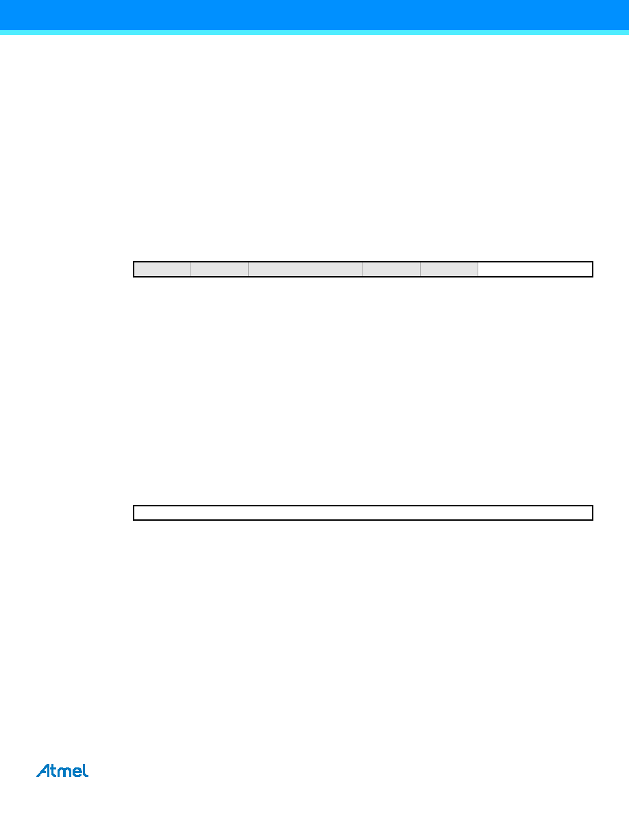
17.3.5 TEMP – Temporary register
Bit 7:0 – TEMP[7:0]: Temporary bits
This register is used for 16-bit access to the counter value, compare value, and TOP value registers. The low byte of the
16-bit register is stored here when it is written by the CPU. The high byte of the 16-bit register is stored when the low byte
is read by the CPU. For more details, refer to “Accessing 16-bit Registers” on page 12.
Bit
7
65
43
210
+0x03
–
COMPIF
OVFIF
Read/Write
R
R/W
Initial Value
0
00
000
Bit
7
65
43
2
1
0
+0x04
TEMP[7:0]
Read/Write
R/W
Initial Value
0
发布紧急采购,3分钟左右您将得到回复。
相关PDF资料
21FMN-BMTTR-A-TB
CONN FMN HSNG 21POS STAG REV SMD
PIC16LF87-I/ML
IC MCU FLASH 4KX14 EEPROM 28QFN
PIC24HJ32GP204-I/PT
IC PIC MCU FLASH 32K 44TQFP
20FMN-BMTTR-A-TB
CONN FMN HSNG 20POS STAG REV SMD
PIC16F88-I/SS
IC MCU FLASH 4KX14 EEPROM 20SSOP
18FMN-BMTTR-A-TB
CONN FMN HSNG 18POS STAG REV SMD
17FMN-BMTTR-A-TB
CONN FMN HSNG 17POS STAG REV SMD
PIC18LF46J11-I/ML
IC PIC MCU FLASH 64K 2V 44-QFN
相关代理商/技术参数
PIC18F4450T-I/ML
功能描述:8位微控制器 -MCU 16KB FL 768 RAM 34 I/O FS-USB 2.0 RoHS:否 制造商:Silicon Labs 核心:8051 处理器系列:C8051F39x 数据总线宽度:8 bit 最大时钟频率:50 MHz 程序存储器大小:16 KB 数据 RAM 大小:1 KB 片上 ADC:Yes 工作电源电压:1.8 V to 3.6 V 工作温度范围:- 40 C to + 105 C 封装 / 箱体:QFN-20 安装风格:SMD/SMT
PIC18F4450T-I/PT
功能描述:8位微控制器 -MCU 16KB FL 768 RAM 34 I/O FS-USB 2.0 RoHS:否 制造商:Silicon Labs 核心:8051 处理器系列:C8051F39x 数据总线宽度:8 bit 最大时钟频率:50 MHz 程序存储器大小:16 KB 数据 RAM 大小:1 KB 片上 ADC:Yes 工作电源电压:1.8 V to 3.6 V 工作温度范围:- 40 C to + 105 C 封装 / 箱体:QFN-20 安装风格:SMD/SMT
PIC18F4455-BL
制造商:POWERLITE SYSTEMS 功能描述:PIC18F445 W/ BOOTLOADER FOR FLASHLAB 制造商:POWERLITE SYSTEMS 功能描述:PIC18F445 W/ BOOTLOADER, FOR FLASHLAB 制造商:POWERLITE SYSTEMS 功能描述:PIC18F445 W/ BOOTLOADER, FOR FLASHLAB; Silicon Manufacturer:Powerlite Systems; Core Architecture:PIC; Kit Contents:Board; Features:Bootloader Programming, RS232 Connector for Boot-Loading and Serial Comms ;RoHS Compliant: Yes
PIC18F4455-I/ML
功能描述:8位微控制器 -MCU 24kBF 2048RM FSUSB2 RoHS:否 制造商:Silicon Labs 核心:8051 处理器系列:C8051F39x 数据总线宽度:8 bit 最大时钟频率:50 MHz 程序存储器大小:16 KB 数据 RAM 大小:1 KB 片上 ADC:Yes 工作电源电压:1.8 V to 3.6 V 工作温度范围:- 40 C to + 105 C 封装 / 箱体:QFN-20 安装风格:SMD/SMT
PIC18F4455-I/P
功能描述:8位微控制器 -MCU 24kBF 2048RM FSUSB2 RoHS:否 制造商:Silicon Labs 核心:8051 处理器系列:C8051F39x 数据总线宽度:8 bit 最大时钟频率:50 MHz 程序存储器大小:16 KB 数据 RAM 大小:1 KB 片上 ADC:Yes 工作电源电压:1.8 V to 3.6 V 工作温度范围:- 40 C to + 105 C 封装 / 箱体:QFN-20 安装风格:SMD/SMT
PIC18F4455-I/PT
功能描述:8位微控制器 -MCU 24kBF 2048RM FSUSB2 RoHS:否 制造商:Silicon Labs 核心:8051 处理器系列:C8051F39x 数据总线宽度:8 bit 最大时钟频率:50 MHz 程序存储器大小:16 KB 数据 RAM 大小:1 KB 片上 ADC:Yes 工作电源电压:1.8 V to 3.6 V 工作温度范围:- 40 C to + 105 C 封装 / 箱体:QFN-20 安装风格:SMD/SMT
PIC18F4455T-I/ML
功能描述:8位微控制器 -MCU 24kBF 2048RM FSUSB2 RoHS:否 制造商:Silicon Labs 核心:8051 处理器系列:C8051F39x 数据总线宽度:8 bit 最大时钟频率:50 MHz 程序存储器大小:16 KB 数据 RAM 大小:1 KB 片上 ADC:Yes 工作电源电压:1.8 V to 3.6 V 工作温度范围:- 40 C to + 105 C 封装 / 箱体:QFN-20 安装风格:SMD/SMT
PIC18F4455T-I/PT
功能描述:8位微控制器 -MCU 24kBF 2048RM FSUSB2 RoHS:否 制造商:Silicon Labs 核心:8051 处理器系列:C8051F39x 数据总线宽度:8 bit 最大时钟频率:50 MHz 程序存储器大小:16 KB 数据 RAM 大小:1 KB 片上 ADC:Yes 工作电源电压:1.8 V to 3.6 V 工作温度范围:- 40 C to + 105 C 封装 / 箱体:QFN-20 安装风格:SMD/SMT